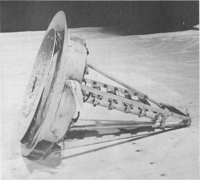
43. Surveyor.
43. Surveyor.
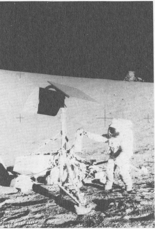
44. Apollo 12 crewman examines Surveyor 3, which soft-landed on the Moon on April 19, 1967. The Apollo 12 (1969) Lunar Module is in the background.
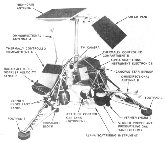
The Surveyor Project, begun in 1960, consisted of seven unmanned spacecraft which were launched between May 30, 1966, and January 6, 1968. The craft were used to develop lunar soft-landing techniques, to survey potential Apollo landing sites, and to improve scientific understanding of the Moon.
Five of the seven Surveyor spacecraft successfully landed on the Moon and performed their tasks well. They responded to 600,545 commands from Earth and returned 87,632 television images of their lunar surroundings. (Surveyors 2 and 4 crashed into the Moon and were destroyed.)
Besides returning TV images, Surveyors 3, 5, 6, and 7 carried a soil-sampling claw which could dig a trench, and test soil hardness and other characteristics. The soil-sampler tests showed that the lunar surface would bear the weight of an Apollo Lunar Module.
Surveyors 5, 6, and 7 carried instruments capable of making simple chemical analyses of the lunar soil near the spacecraft. This information told scientists that most lunar soil near the Surveyors was basalt, a common rock on Earth as well.
The Surveyor spacecraft on exhibit, designated S-10, was used in ground-based tests of on-board equipment, and was not used on a mission. S-10 is exhibited as it would have appeared just before landing on the Moon.
Prime contractor for the Surveyor spacecraft was the Hughes Aircraft Company. The project was managed by the National Aeronautics and Space Administration, Jet Propulsion Laboratory, California Institute of Technology, Pasadena, California.
The spacecraft on exhibit is from the National Aeronautics and Space Administration.
| Height | 3 m. (10 ft.) |
| Distance across footpads | 3.5 m. (11 ft., 6 in.) |
| Weight | 1000 kg. (2204 lb.) at launch; 292 kg. (644 lb.) as exhibited |
| Electrical power | One .83 sq. m. (9 sq. ft.) solar panel providing 89 w. to a silver-zinc battery |
| Landing vernier rocket system | Three throttleable liquid-propellant rockets each providing from 14.6 to 47.2 kg. thrust (30 to 104 lb. thrust). Fuel—Monomethylhydrazine monohydrate; oxidizer 90% nitrogen tetroxide and 10% nitric oxide. |
The American pioneer of astronautics, Robert H. Goddard (1882-1945) not only outlined the physical principles that would govern space flight, but he also constructed and tested many rocket engines, airframes, control devices, and guidance mechanisms between 1926 and 1942.
Goddard held a doctorate in physics, and was a professor at Clark University, Worcester, Massachusetts. The Smithsonian Institution began funding Goddard’s experiments as early as 1917 and published his first major work, A Method of Reaching Extreme Altitudes, in 1919.
Goddard was not only a trained scientist, but a talented and ingenious engineer as well. On March 16, 1926, he launched the world’s first liquid-propellant rocket. By 1930, he had established a rocket test facility at Mescalero Ranch, near Roswell, New Mexico. Here, he conducted research, funded by the Daniel and Florence Guggenheim Foundation, on rocket power plants, pumps and fuel systems, control mechanisms, and other vital elements of the modern rocket.
This vehicle is the oldest surviving liquid-propellant rocket in the world. Built of parts employed in the first liquid-propellant rocket launched on March 16, 1926, the engine was moved from the nose of the vehicle to the rear for the May 4 trial. Other changes were introduced to reduce the weight of the rocket to 2.5 kilograms (5.5 pounds). The motor burned gasoline and liquid oxygen.
The alcohol burner under the liquid oxygen tank was inadvertently not ignited, causing the May 4 attempted launch to fail. A second test on May 5 also proved unsuccessful. However, the rocket engine was fired on both occasions.
The May 4 rocket is from Mrs. Robert H. Goddard and the Daniel and Florence Guggenheim Foundation.
| May 1926 rocket | |
|---|---|
| Length | 1.95 m. (6 ft., 4 in.) |
| Weight | 2.5 kg. (5.5 lb.) |
| Fuel | Gasoline |
| Oxidizer | Liquid oxygen |
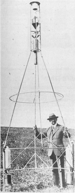
45. Dr. Goddard and the “Hoopskirt.” Propellant tanks are on legs of frame.
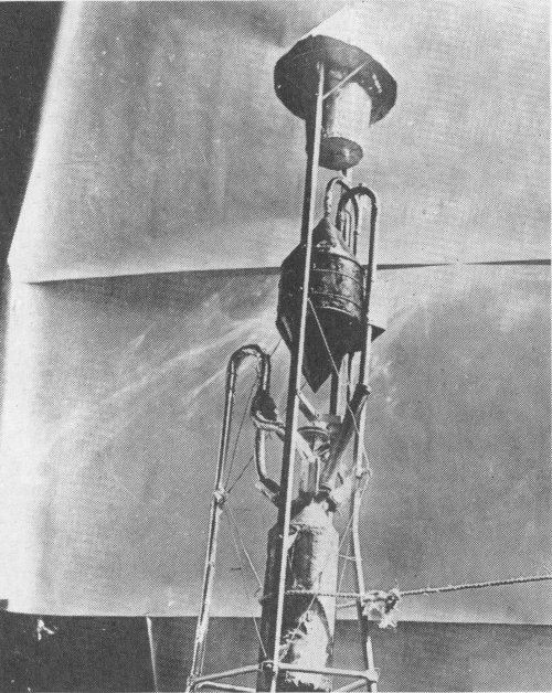
46. The upper section of the “Hoopskirt” rocket.
Developed by Dr. Goddard during the late summer and early fall of 1928, the “Hoopskirt” rocket featured a small rocket engine mounted in the nose and a system of tanks and alcohol burners—to maintain fuel pressure—mounted on two legs. On December 26, 1928, the rocket flew 62.33 meters (204.5 feet) in 3.2 seconds—its most successful flight. Like all Goddard rockets, the “Hoopskirt” burned gasoline and liquid oxygen.
The “Hoopskirt” rocket is from Mrs. Robert H. Goddard.
| “Hoopskirt” | |
|---|---|
| Height | 4.5 m. (14 ft., 8 in.) |
| Weight | 12.93 kg. (28.5 lb.) |
| Fuel | Gasoline |
| Oxidizer | Liquid oxygen |
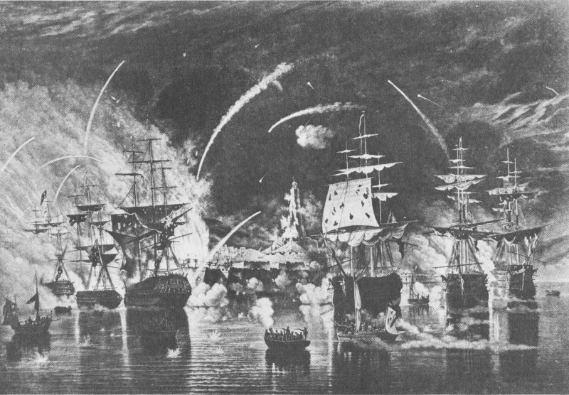
47. The Bombardment of Algiers, 1816. Congreve rockets in use.
The rebirth of European interest in military rocketry can be traced to the English conquest of India during the late 18th century. William Congreve, an artillery expert, was intrigued by the tactical success of the Indian war rockets. He began a research program in 1804 that led to the development of a metal-cased, stick-guided artillery rocket that could be fired in barrages against enemy troops. The rocket carried incendiary or explosive warheads.
The 14.5-kilogram (32-pound) Congreve war rocket models on display show the early side-mounting of the stabilizing guide stick and the later (1815) design in which the guide stick was center-mounted to give greater accuracy. Congreve rockets played an important role during the Napoleonic Wars and the War of 1812.
The experimental 45.4-kilogram (100-pound) Congreve incendiary rocket was developed as a siege weapon for use against fortresses or entrenched enemy positions, although it is not known to have been used in combat. The 6.7-meter (22-foot) guide stick screwed together and fitted to the side of the projectile before firing. Like the smaller Congreve rockets, it could be launched from a frame or earthen embankment.
William Hale was an English engineer and ordnance expert who made cumbersome guide sticks obsolete with the introduction of spin stabilization to rocketry. Hale’s first design of a stickless, or rotary, rocket was patented in 1844. Although the 5.4-kilogram (12-pound) rocket was used during the Mexican War (1846-1847) and the Civil War, Hale subsequently refined it because the rocket had a tendency to oscillate in the air following exhaustion of the propellant.
Hale’s intermediate pattern rocket of 1862—on display—was never produced, giving way in 1865 to a rocket weighing 11 kilograms (24 pounds) with a maximum range of 2012 meters (2200 yards) when fired from a 4.6-meter (15-foot) elevation. The propellant burned for 5 to 10 seconds, producing an estimated maximum thrust of 136 kilograms (300 pounds).
The American version of the Hale rocket has two sets of gas nozzles. The major aperture on the base of the case allowed the propellant gases to escape. The smaller holes above the rocket’s midpoint are angled; the exhaust gases spin the projectile, stabilizing it during flight. Hale rocket designs were employed by both sides during the Civil War.

48. Hale rocket with canted nozzles for spin-stabilization.
The Congreve 14.5-kilogram (32-pound) war rocket model was copied from the original at the Royal Artillery Institution; the experimental Congreve incendiary rocket on display is a gift of that Institution. Hale’s 1844 design rocket, his 1862 experimental rocket, and the 1865 rocket are on loan from the Science Museum, London. The American Hale rocket is on loan from F. C. Durant III.
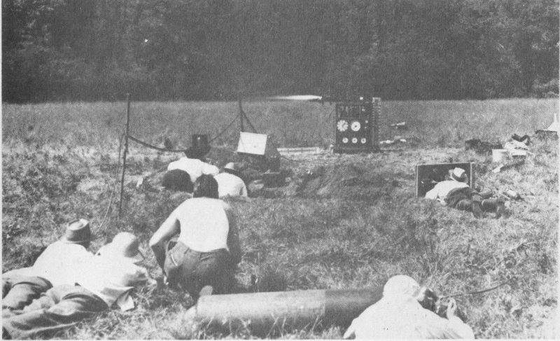
49. Static test of liquid-fuel rocket engine on American Rocket Society Test Stand No. 2.
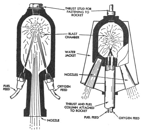
50. Two early types of liquid-fuel, rocket motors. Left, the original ARS motor; right, a four-nozzle motor for ARS No. 4 rocket.
The American Rocket Society (ARS) was the first organization in the United States dedicated to rocket research. The society was founded in New York City in March 1930 by G. E. Pendray and David Laser. The first successful ARS rocket was launched on May 13, 1933. The group continued to build and test rocket engines until the outbreak of World War II. After 1945, the ARS became a professional society for engineers involved in astronautics. The ARS joined with other aeronautical engineering groups to form the American Institute of Aeronautics and Astronautics in 1963.
The first liquid-propellant rocket engines built by the American Rocket Society were machined from blanks of heat-resistant, cast-aluminum alloy. Engine No. 1 powered the first two rockets designed and constructed by the ARS. It featured combustion chamber walls 12.7 millimeters (½ inch) thick and burned liquid oxygen and gasoline to produce a thrust of 27.22 kilograms (60 pounds). Liquid oxygen was pressurized by partial evaporation, while bottled nitrogen forced gasoline from the tank to the engine.
ARS Engine No. 4, like its predecessors, was mounted in the nose, rather than the tail, of the rocket. The engine featured a single combustion chamber and four nozzles. The nozzles directed the jet gases to the rear and slightly away from the top of the gasoline tank on which the engine was mounted. The rocket powered by this engine was tested on September 9, 1934. It rose several hundred feet, at which point one of the nozzles burned out, bringing the flight to a close. In 1938, ARS member James Wyld suggested a cooling system whereby propellants circulate through a jacket surrounding the combustion chamber. Engines using this system are termed “regeneratively cooled.” The first Wyld rocket motor tested developed 41 kilograms (90 pounds) of thrust for 13½ seconds. It proved so successful that Wyld and other members of the ARS founded Reaction Motors, Inc., to produce and sell rocket engines based on this design.
The performance of motors developed by the ARS prior to World War II was measured on a test stand with built-in fuel and oxidizer tanks and bottled nitrogen gas. The engine was mounted on a carriage, and connected to the stand’s propellant tanks by flexible metal hoses. Thrust was indicated on a pressure gauge. The stand was first used in 1938.
All American Rocket Society artifacts are from G. E. Pendray and the American Institute of Aeronautics and Astronautics.
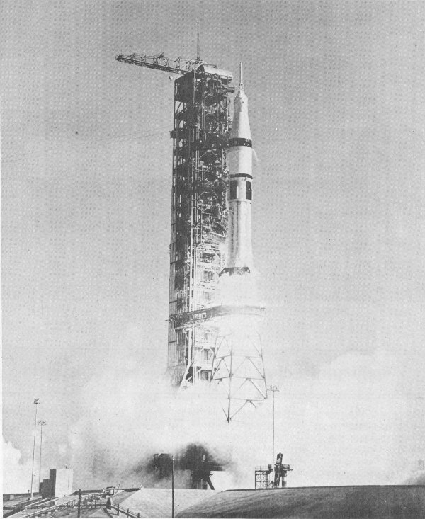
51. A two-stage Saturn 1B rocket powered by H-1 engine cluster lifts off carrying Skylab 4 astronauts, November 16, 1973.
The H-1 liquid-propellant rocket engine was an outgrowth of the LR-79 which served as the basic power plant for the USAF Thor missile. The H-1 was used in the 8-engine cluster of the first stage of the Saturn 1 and 1B launch vehicles.
The H-1 burns liquid oxygen and a grade of aviation kerosene to produce a total thrust of 92,986 kilograms (205,000 pounds). Each engine functions as an independent unit, with its own combustion chamber and turbopump, but fuel is drawn from common tanks.
The Saturn 1B was first launched on February 26, 1966, and most recently on July 15, 1975, in the launch of the U.S. crew of the Apollo-Soyuz Test Project.
It was developed by Rocketdyne, a division of North American Rockwell Corporation.
The engine on exhibit is from the National Aeronautics and Space Administration.

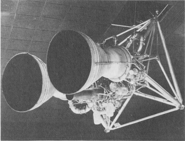
52. RL-10 engines used to power Centaur launch vehicle.
The RL-10 is an upper stage propulsion system that can be stopped and restarted in space. It is a regeneratively cooled engine which burns liquid hydrogen and liquid oxygen to produce 6800 kilograms (15,000 pounds) of thrust. RL-10s pioneered the use of liquid hydrogen as a rocket fuel. They powered the Centaur launch vehicles that boosted such craft as Surveyor and Viking into space. A six-engine cluster of RL-10s was also used to propel the S4 stage of the Saturn 1.
The RL-10 was developed by Pratt & Whitney Aircraft division of the United Aircraft Corporation.
The RL-10 engine is from the National Aeronautics and Space Administration.
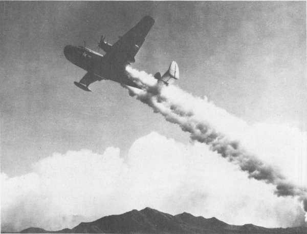
53. JATO-boosted Martin Mariner aircraft.
JATO (Jet Assisted Take-Off) rockets boost heavy aircraft from short runways or from high-altitude airports where long take-off runs are required. The development of more powerful airplane engines has reduced the use of JATOs in recent years.
The first American JATO units were tested at March Field, California, on August 12, 1941. Six solid-propellant engines, each developing 12.8 kilograms (28 pounds) of thrust, boosted a light plane piloted by Capt. Homer Boushey into the air on this occasion. These motors were designed and built by staff members of the Air Corps Jet Propulsion Research Project of the Guggenheim Aeronautical Laboratory of the California Institute of Technology.
During World War II, work continued on JATO prototypes: the M17G was developed by Reaction Motors, Inc., to provide 590 kilograms (1300 pounds) of thrust to assist the take-off of PBM flying boats; the M19G, also built by Reaction Motors, Inc., was fueled by gasoline with liquid oxygen as an oxidizer.
The liquid-propellant 25ALD1000, developed during World War II. produced 453 kilograms (1000 pounds) of thrust and burned red-fuming nitric acid as an oxidizer and aniline as a fuel. It was successfully used on a variety of aircraft, including the B-24, B-25, C-40, and P-38.
After the war ended, JATO engines were used on military aircraft such as the B-47 and F-84 in the United States, while in Britain the JATO Super Sprite became the first rocket engine to receive official type approval for quantity production.
The first U.S. JATO unit and the 25ALD1000 are gifts of the Aerojet General Division of the General Tire and Rubber Company. The M17G and M19G JATOs are from the Thiokol Chemical Corporation, and Rolls Royce, Ltd., provided the Super Sprite.
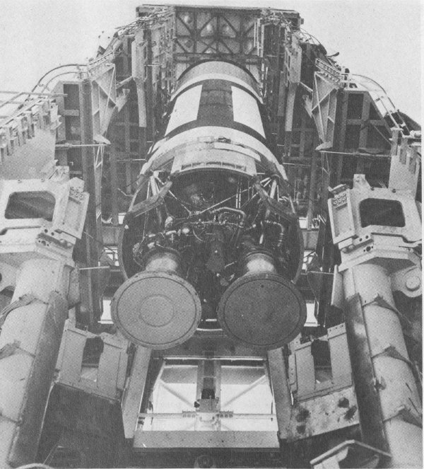
54. LR-87 engine in Titan on launch stand.
The LR-87 was a twin-chamber liquid-propellant rocket engine developed to power the Titan I intercontinental ballistic missile. The engine developed a total thrust of 136,078 kilograms (300,000 pounds) at sea level. It burned liquid oxygen and a grade of aviation kerosene. The combustion chambers were gimbal mounted to allow them to swivel, controlling the missile trajectory during the powered phase of flight. The engine was developed by Aerojet General Corporation.
55. LR-87 engine just after suspension in the museum.
The LR-87 on exhibit is from the U.S. Air Force.
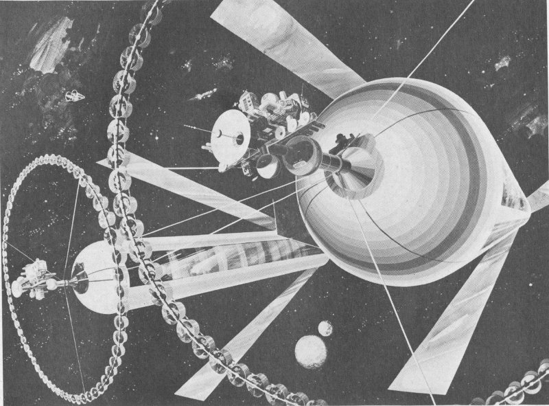
56. A 21st-century space colony in orbit between Earth and the Moon, as suggested by Dr. Gerard O’Neill of Princeton University. This colony could accommodate 200,000 persons, using solar energy for power and lunar or asteroid materials for construction. The teacup-shaped containers ringing the cylinder are agricultural stations, and the mirrors would direct sunlight into the interior, regulate the seasons, and control the day-night cycle.
During the first twenty years of the space age, all launch vehicles were propelled by solid or liquid chemical rockets; however, nuclear and electric rocket motors are needed to provide the higher thrusts and velocities required for possible future manned journeys to other planets. Robert H. Goddard, the American rocket pioneer, was the first to suggest the possibility of electric rocket motors, but it was not until 1964 that electric rockets were actually tested in space.
Two types of ion engines represent the most fully developed electric propulsion systems. In contact ion engines, a propellant gas (mercury or cesium, for example) is ionized, or given an electrical charge, by passage through a hot porous metal. The resulting ions are accelerated out of the engine by an electrical field. The charged ions are neutralized as they approach the nozzle to form an exhaust beam that imparts the thrust. Bombardment ion engines rely on the bombardment of the propellant gas by electrons from a cathode, or negative electrode, to create ions. The ions are accelerated from the engine in the same manner as in the contact ion engine.
This small contact ion engine produces .0009 kilogram (.002 pound) of thrust by passing vaporized cesium through hot tungsten. On Earth this amount of power is scarcely enough to lift a one-carat jewel an inch off a table, but in the frictionless vacuum of space, it is sufficient to provide attitude control for satellites. It can also accelerate a spacecraft to high interplanetary velocities by operating continuously for thousands of hours.
An ion engine of this type was first tested in space in 1964. On that occasion, it provided .0009 kilogram (.002 pound) of thrust for 2 hours, 10 minutes. It was able to control the attitude of the attached instrument package.
This ion engine is a gift from Electro-Optical Systems, Inc., the company that developed it.
57. The Project Orion test vehicle was used to explore the feasibility of a unique type of propulsion which utilized successive nuclear explosions behind the rear pusher plate.
Project Orion was an attempt to solve the problems of propulsion for long-term manned journeys to other planets by creating an engine that would use successive nuclear explosions to propel very large space vehicles. The Orion spacecraft was designed to carry many small nuclear explosive systems which would be ejected sequentially from the rear of the vehicle. These units would explode some distance behind the spacecraft. The expanding debris, in the form of high-velocity, high-density plasma, would strike a pusher plate at the rear of the Orion vehicle.
Work on Project Orion was halted in 1963 when the Limited Nuclear Test Ban Treaty, which prohibited atmospheric tests of the propulsion system, was signed.
The Project Orion Test Vehicle—on display—demonstrated the basic principle of intermittent thrust from explosive charges. Test data provided by this model would have assisted engineers in developing the full-scale spacecraft.
The test vehicle carried five high-explosive plastic charges which were ejected from the rear of the craft. Compressed nitrogen powered the ejection system. Each charge was attached to the vehicle by a .9-meter (3-foot) cord. A microswitch exploded the individual packages. The Project Orion Test Vehicle was first flown successfully in October 1959.
From the Gulf Energy and Environmental Systems, Inc.
Although this engine is a liquid-propellant rocket, it substitutes a series of small combustion chambers and nozzles for the traditional single large chamber and nozzle to achieve additional thrust. This innovative combustion system features chambers and nozzles mounted on an annular ring at the base of the engine. Thrust is derived from the expansion of the exhaust gases against a large segmented plug in the center of the engine. Flight control is achieved by varying the amount of propellant introduced into the individual chamber sections. The engine on exhibit burned liquid oxygen and kerosene to provide a thrust of 22,680 kilograms (50,000 pounds).
The plug-nose rocket engine was developed at the General Electric Company’s Malta Test Station in 1961.
The engine on exhibit is from the New York State Atomic and Space Authority.
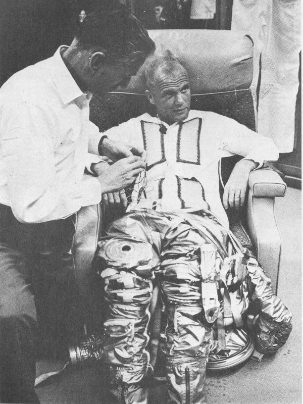
58. Astronaut John Glenn is assisted with his suiting-up.
Modern space suits are direct descendants of the simple “pressure suits” designed as early as 1907 for deep-sea divers. In 1911 an English respiratory physiologist, J. S. Haldane, proposed the use of an oxygen pressurized suit for ascent to high altitudes. The first U.S. patent was granted for a pressure suit in 1918.
Through the early 1960s, all such suits were pressure containers. Project Mercury astronauts wore suits adapted from the U.S. Navy MK-IV pressure suit. It consisted of an inner layer of neoprene-coated fabric and a restraint layer of aluminized nylon fabric. The garment design provided a fair degree of mobility, although the suit could not bend with the full hinge motion of the human elbow or knee because it folded in at the joints, reducing overall volume and increasing internal pressure. The Mercury suit would have been pressurized only if spacecraft cabin pressure had been lost.
Space suits require a great deal of sophistication. They must meet many vital criteria, including low leakage, thermal control, comfort, stowage, and protection from micrometeoroid strikes.
Gemini 4 was the first American mission to explore the problems of man functioning outside his spacecraft, with only his space suit for protection. This extravehicular activity required the space suit to be a prime system rather than a precautionary measure.
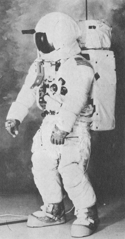
59. Apollo space suit.
Designed and created primarily for moon-walking, the 28.6-kilogram (63-pound) Apollo space suits, with backpack environmental and communication systems, enabled the lunar astronauts to dispense with the tether used on the Gemini “spacewalks.” The suit’s 21 layers are materials such as teflon fabric, nonwoven dacron, and aluminized mylar. These alternating layers of specialized materials protected the astronauts from the extreme temperatures of space and possibility of micrometeroids striking. Boots and gloves contain a stainless steel cloth to protect against abrasion. Suits had to fit the wearers so precisely that 67 anthropometric measurements were required of each astronaut.
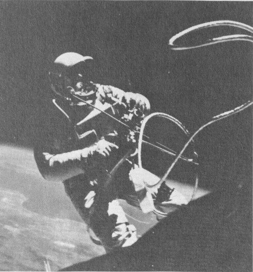
60. Astronaut White takes the first “spacewalk” with only his suit for protection from the space environment.
When the astronauts ventured outside the spacecraft and explored the lunar surface, the following equipment was worn under the suit: a fecal containment system for emergency containment of solid-waste material; a liquid-cooling garment; a bio-belt assembly, urine collection and transfer system. Together with a portable life-support system, this constituted the complete Environmental Mobility Unit (EMU).
The liquid-cooling garment consists of an outer layer of nylon spandex material, a network of polyvinyl-chloride tubing, and a nylon-chiffon comfort liner. Even spacing of the plastic tubing permitted the efficient transfer of body heat to the cooling liquid (water) as it circulated through the suit.
The bio-belt assembly, worn over the liquid-cooling garment, contains preamplifiers for sensors placed next to the skin. The sensors acquired electrical signals which determined respiration rate and electrocardiograms of the astronauts. The preamplifiers relayed the signals to the spacecraft telemetry system for transmission to Earth.
The urine collection and transfer assembly provided for emergency containment of liquid waste when spacecraft facilities were not available. Liquid waste was subsequently transferred from the collection assembly to the spacecraft waste-management system.
The portable life-support system (PLSS) created and maintained a livable atmosphere inside an astronaut’s space suit during activity on the lunar surface. Worn as a backpack, the PLSS could be used for as long as four hours at a time.
The PLSS supplied oxygen for breathing purposes, suit pressurization, and ventilation. It also removed contaminants from oxygen circulating through the suit and supplied water and oxygen for body cooling. Conversion of exhaled carbon dioxide into oxygen was accomplished through a lithium-hydroxide cartridge also contained in the PLSS. An emergency supply of oxygen was contained in the oxygen purge system mounted on top of the PLSS.
When fully charged, the pack weighs 38 kilograms (84 pounds) on Earth or 6.3 kilograms (14 pounds) on the Moon.
The space suit on exhibit is from the National Aeronautics and Space Administration.
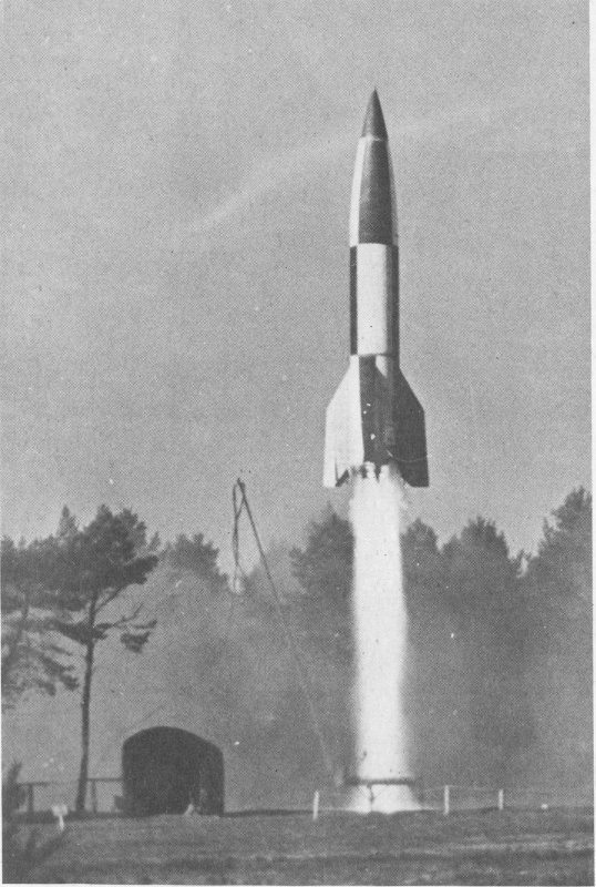
61. British-supervised postwar launch of V-2 in Germany.
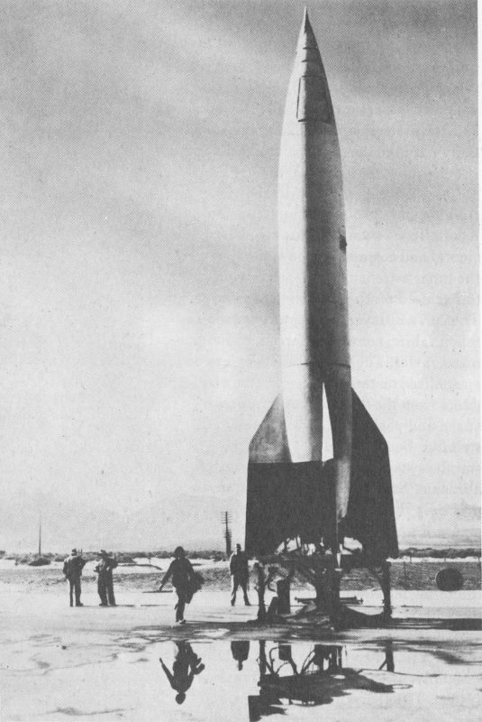
62. V-2.
The German V-2, originally designated A-4, represents the beginning of modern rocketry. The V-2 was the first proof that large rockets of the sort described by the space-flight pioneers of the early twentieth century could be successfully built and flown. It was also the forerunner of the intercontinental ballistic missile system.
Developed by a team of engineers working under the direction of Dr. Wernher von Braun at Peenemunde, Germany, the V-2 work laid the foundation for the Redstone missile through the Saturn series of space launch vehicles.
Four-thousand V-2s were fired against Allied targets in England and on the continent in 1944 and 1945. After World War II, captured V-2 rockets were used to train American technicians in missile launch procedures and to carry the first payloads of scientific instruments into the upper atmosphere in the United States.
The operational V-2 rocket structure consisted of three sections. The nose housed the warhead and control mechanisms. The fuel tanks carried liquid oxygen and alcohol propellants. The rocket engine, turbopumps, and control surfaces were contained in the tail section.
Jet deflector vanes positioned in the stream of exhaust gases and external vanes maintained attitude and directional control during the powered portion of flight.
| Length | 14 m. (46 ft., 1 in.) |
| Diameter | 1.6 m. (5 ft., 5 in.) |
| Propellants | Alcohol and liquid oxygen |
| Thrust | 25,400 kg. (56,000 lb.) |
| Velocity | 5633 km./hr. (3500 mi./hr.) |
| Altitude | Peak of operational trajectory, 89 km. (55 mi.) |

63. Illustration from World War II intelligence report.
The German-developed V-1 was an automatically controlled pilotless aircraft for use against Allied cities during World War II.
The missile was launched from ground ramps. Once in the air, automatic controls on board the craft took over. The V-1 climbed to a predetermined altitude, followed a compass course, and dove to the ground after a preset distance had been covered.
This mid-wing monoplane was powered by a unique pulsejet engine above the rear portion of the fuselage.
The relatively low speed of the missile made it easy prey for antiaircraft guns or fighters.
The V-1 on exhibit is from the U.S. Air Force, Park Ridge Depot.
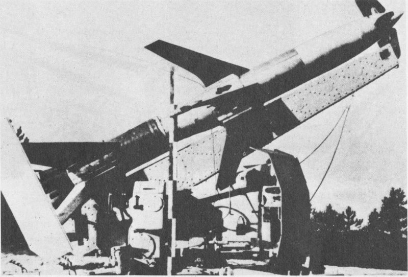
64. Rheintochter R-I (Rhine Maiden).
The Rheintochter I (Rhine Maiden) was intended for use against Allied bomber formations late in World War II. The German ground-to-air rocket was fin-stabilized, and controlled by radio. The flight of the two-stage vehicle was controlled by the four movable vanes on the nose of the craft.
The first stage carried the missile away from the launching rail, while the second stage brought the missile up to full speed and propelled it to the target.
Both the booster and sustainer engines used solid fuel. After a six-tenths of a second burn, the booster dropped off and the sustainer motor ignited. The missile warhead was housed at the rear of the sustainer stage. Exhaust gases were expelled through six nozzles located between the main fins.
The program was abandoned in December 1944, after 82 Rheintochter I rockets had been test fired. By then it had become apparent that the missile could not reach the operational altitude of modern bomber aircraft.
65. Hs-298.
The Hs-298 was designed to combat the Allied bomber threat to wartime Germany. This air-to-air missile could be launched from either fighter or bomber aircraft and was in quantity production early in 1945.
It carried 45.4 kilograms (100 pounds) of high explosives that were detonated by proximity fuse when the missile was within 9.1 meters (30 feet) of an enemy airplane.

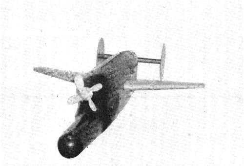
66. X-4.
The fin-stabilized X-4 air-to-air missile was guided to its target by means of electrical impulses which passed through two wires connecting the rocket to the launch aircraft until detonation. Once the missile was on its way to the target bomber, the fighter pilot directed its course with a separate small control stick in his cockpit. Because the control wires streamed out ahead of the launching aircraft, the pilot was prevented from evasive maneuvering.
Launched from German fighter aircraft, usually a FW-190, the X-4 was powered by either a solid-propellant engine or a bi-propellant liquid-rocket engine. It carried a 20-kilogram (44-pound) warhead.
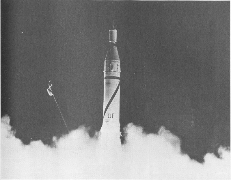
67. Jupiter-C launches the first American satellite, January 31, 1958.
Jupiter-C carried the first successful American artificial earth satellite, Explorer 1, into orbit on January 31, 1958. Jupiter-C launched additional Explorer satellites on March 26 and July 26, 1958.
Jupiter-C, or Juno 1, is a modified version of the Redstone Ballistic Missile and a direct descendant of the V-2 (A-4) rocket developed in Germany during the second World War.
The vehicle’s main stage is powered by a rocket engine burning liquid oxygen and a hydrazine mixture. The second and third stages are contained in the “tub” on the nose of the rocket. Both use scaled-down Sergeant solid-propellant rockets: eleven in the second stage and three in the third. A final Sergeant motor is attached to the base of the satellite to provide the velocity necessary to place the vehicle in orbit. An electric motor spun the entire “tub” prior to launch and during the climb into space in order to stabilize the satellite.
The Jupiter-C was built by the U.S. Army Ballistic Missile Agency.
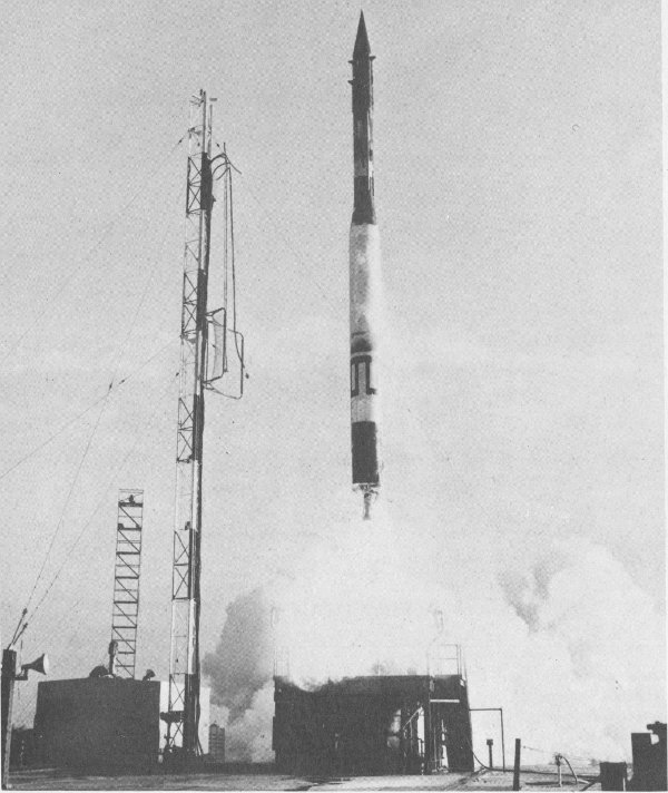
68. Three-stage Vanguard launch vehicle boosts the second American satellite into Earth-orbit, March 17, 1958.
Standing 21.6 meters (70.8 feet) high and weighing more than 10,000 kilograms (20,000 pounds), the Vanguard launch vehicle successfully orbited three satellites. The first was Vanguard 1, launched on March 17, 1958.
The rocket has three stages. The first-stage motor, burning kerosene and liquid oxygen, operated for 2 minutes and 20 seconds. The second stage carried the vehicle to an altitude of 210 kilometers (130 miles), propelled by white-fuming nitric acid and unsymmetrical dimethylhydrazine (UDMH). With propellants exhausted, the upper stages then coasted to 480 kilometers (300 miles) above the surface of the Earth where the solid-propellant third-stage motor fired to place the satellite into orbit.
The Vanguard was designed and built by the Martin Company for the U.S. Naval Research Laboratory.
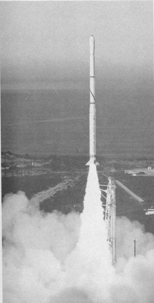
69. Four-stage Scout vehicle launches satellite from the Western Test Range, California.
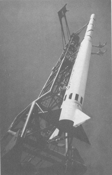
70. Scout in vertical position prior to the launch of an Explorer science satellite, April 29, 1965.
On February 16, 1961, Scout became the first solid-propellant vehicle to orbit a satellite (Explorer 9). It is a four-stage launch vehicle that can perform a variety of space and reentry research tasks. Its relatively low cost has made it a popular choice for many satellite programs, including Transit navigation satellites, the Small Astronomy and Small Scientific Satellites, the Beacon Explorer, Hawkeye, Micrometeoroid, Meteoroid Technology, and Solrad satellites. The rocket has also been used extensively to launch foreign satellites. ANS-A (Netherlands), GRP-A (Germany), UK-5 (England), Eole (France), San Marco 5 (Italy), and the ESRO satellites for the European Space Research Organization (now European Space Agency) have all gone aloft aboard Scout launch vehicles.
The satellite in the nose of the Scout on exhibit is an INJUN/Air Density Explorer identical to that launched from Wallops Island, Virginia, on August 8, 1968.
Scout was built by the LTV Aerospace Corporation for the National Aeronautics and Space Administration and the Department of Defense.
The Scout is from the National Aeronautics and Space Administration and LTV Aerospace Corporation.